Arduino Single power control unit: Difference between revisions
From Yocto Project
Jump to navigationJump to search
| Line 12: | Line 12: | ||
[[File:housemade_relay.png]] | [[File:housemade_relay.png]] | ||
==== | ==== The required hardware ==== | ||
* 1 BJT transistor 2N2222A | * 1 BJT transistor 2N2222A | ||
* 1 3.3 kOhms resistor | * 1 3.3 kOhms resistor | ||
| Line 21: | Line 21: | ||
* 1 male outlet connector and 1 female outlet plug | * 1 male outlet connector and 1 female outlet plug | ||
* 14AWG Wire (as needed) | * 14AWG Wire (as needed) | ||
=== The arduino 101 === | === The arduino 101 === | ||
Revision as of 18:48, 14 December 2016
The Justification
The Arduino Single power control unit was created for controlling a relay that is able to turn on/off the devices that it powers like the Yocto DUTs. Such need has arisen due to a clean power-off has not been always reliable.
The software part
It is required devauto module simplepwsc to control this single power unit. Upon the source directory of this module can be found gen_ard_101.ino to flash the arduino 101
The hardware part
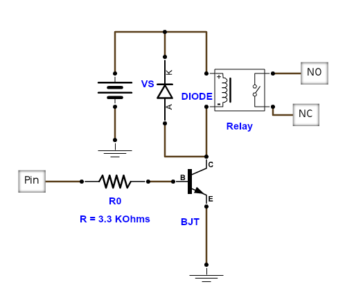
The circuit
In order to build a power cutter using a relay module, one must follow the circuit provided.
The required hardware
- 1 BJT transistor 2N2222A
- 1 3.3 kOhms resistor
- 1 1N4007 diode
- 1 relay module (RAS-0510)
- 1 Protoboard or perforated PCB (min 4.5x4.5 cm)
- 1 Two positions terminal block
- 1 male outlet connector and 1 female outlet plug
- 14AWG Wire (as needed)
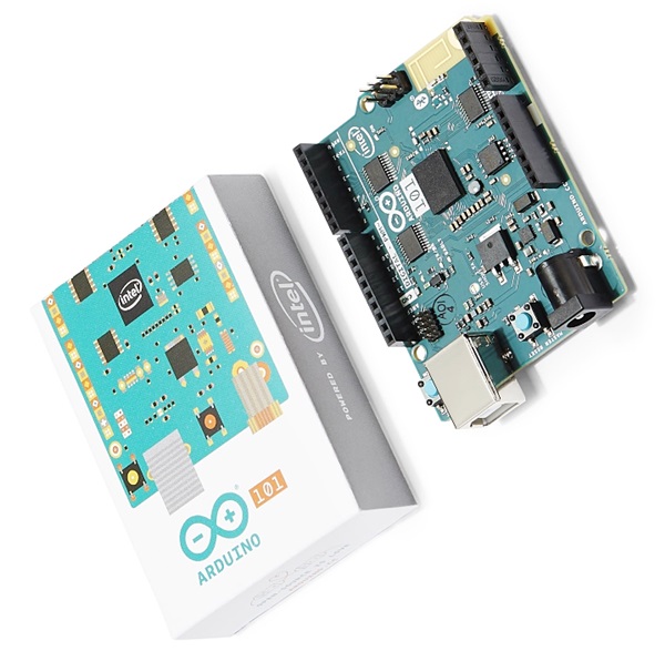
The arduino 101
Configuration for relay cables: 5V (from the board) GND (from the board) Signal (min 3.3V max 5V, from GPIO 13 of board)

